Start with PAS: from installation to useful readings
Follow the steps in order. Check the PC and connection, identify the meter, preserve its setup, then learn how settings affect the readings. Open only the recording for your model.
Guide and available recordings · protected development preview
Move from communication checks to the question you need to answer.
1. Install or check PAS
Install and check PAS
PAS software · 1:22
About this recording
Reused older SATEC recording · Earlier SATEC installation capture; Australian narrated edition, 8 November 2026
This recording shows a full installation and a separate update, then checks the PAS version. It does not demonstrate a backup or a new installation on this computer.
Earlier SATEC footage, edited and narrated with ElevenLabs Michael (Australian). Explanatory held views are labelled. The source displays 09/03/25; its date format has not been established.
Transcript and sources
This earlier recording shows a full PAS installation,
followed by the separate software update.
On the SATEC Australia PAS page, choose the full installation package.
The installation guide is linked alongside the downloads.
Open the downloaded package and choose Extract All.
Open the extracted folder, then launch the setup program to start the installation wizard.
The installation folder shown here is C drive, Pas.
Select Next.
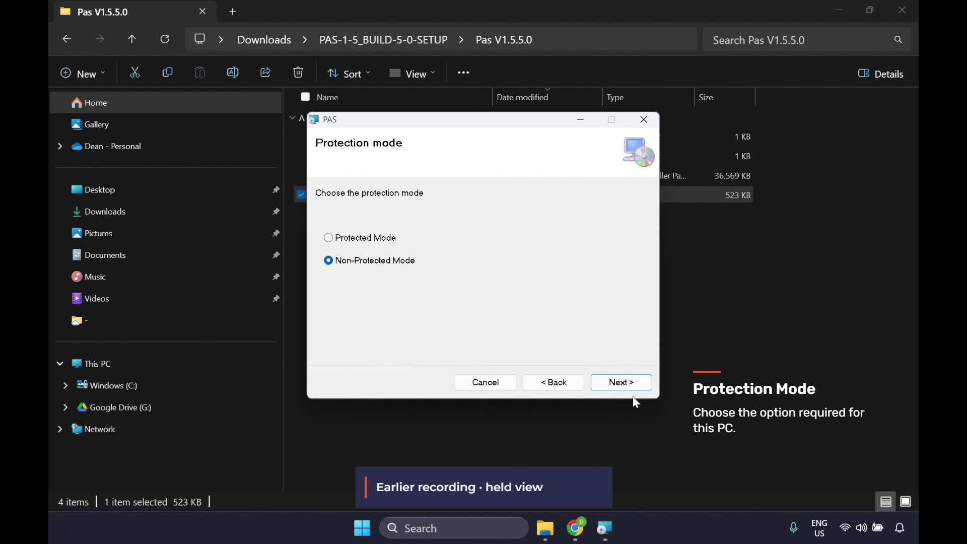
At Protection Mode, choose the option required for this computer.
This example uses non-protected mode.
Protected mode requires a PAS login when the program starts.
Continue through the wizard and let the installation finish.
When Installation Complete appears, close the installer.
Now return to the PAS download page for the separate update.
This package is used after the full installation.
Extract the update and open its folder.
In this example, the update contains the PAS executable.
Copy it into the installed PAS folder, replacing the existing executable.
Keep the destination folder visible so the replacement is clear.
Open PAS and check the version in its title bar.
The installation and update are complete in this recorded example.
With PAS open, the next lesson creates a site and checks communication.
Pro tip: include this version number when asking for PAS support.
If PAS is not installed, open the SATEC Australia PAS software page and follow its installation resources. Use the installer and requirements supplied there.
For a full installation, disconnect SATEC USB devices and run setup.exe as administrator. Use administrator privileges for the first PAS start too. If the installer finds existing setup files, read the preserve-or-replace choice before continuing.
If PAS is already installed, open it and record the displayed software version for your training notes. Keep the current meter disconnected or PAS offline while learning the screen and creating a local site.
Close PAS and preserve its folder, including Sites and PasConfig, together with log databases stored elsewhere. Check the backup before continuing. Read preservation and protection choices against the installation guide.
These are preparation instructions. The historical film does not show every backup or preservation action being completed.
Available: an earlier SATEC installation capture with new narration. Follow the current supplied installation resources; this historical film does not establish compatibility with your PC or demonstrate a complete backup.
Before moving on
PAS opens on your PC and you have noted the version. An open application does not establish a meter connection.
2. Find the Site Tree and the selected meter
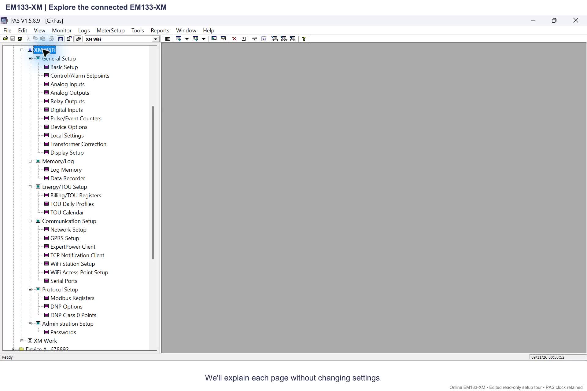
Maximise PAS. Locate the Site Tree, the selected site and the working area. A site is a local database entry; its name alone does not identify a connected meter.
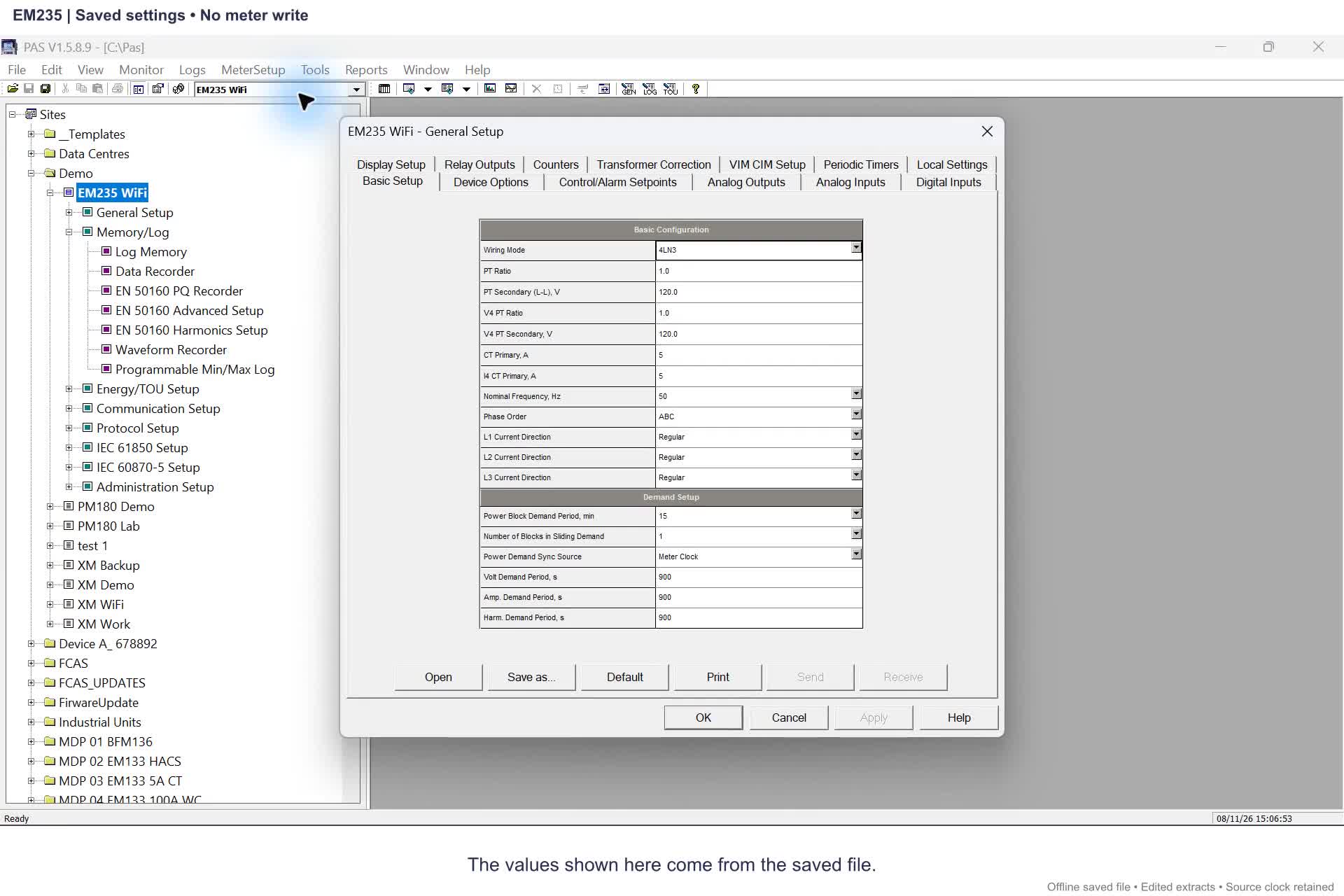
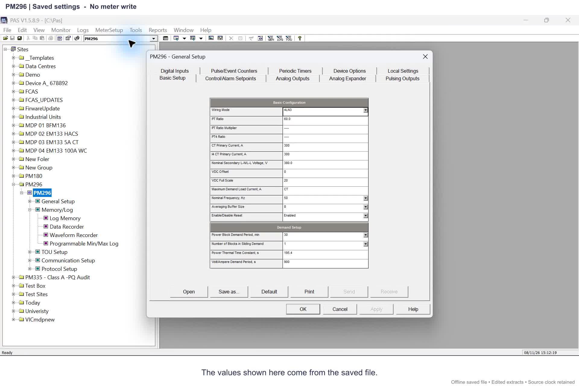
Choose the menu recording for your exact model below. These recordings show offline site files. Keep the model name visible and use the menu route before trying shortcuts.
These menu recordings cover only the named models. If yours is different, use its manual and the general PAS site guide. Similar-looking menus do not establish the same settings or capabilities.
Existing PAS recordings · 8 November 2026 · offline site-file navigation
Before moving on
You can point to the selected site and distinguish its model from the name you gave the file.
3. Choose serial or Ethernet and check Windows
Choose the connection instructions below. For the PM180, PRO and XM network demonstrations, use Ethernet/IP; the PC may reach that network over Wi-Fi. The legacy PM296 demonstration uses a USB–RS-485 converter. A USB converter plugged into the PC is still a serial connection in PAS.
Complete the matching connection check below before opening PAS. Note the actual result; do not copy a COM number or network address merely because it appears in a training example.
Identify the exact meter model and its input options. For a network connection, obtain the meter’s assigned IP address, protocol, host port and device address. For RS-485, obtain its device address, baud rate, parity/data format and protocol, then read the converter’s current COM number in Windows.
A direct USB cable to a meter’s own USB port is a different connection from USB–RS-485. Do not select USB Port in PAS just because the serial converter uses a USB socket on the PC.
A reply to ping establishes IP reachability at that moment. It does not identify the meter or test its Modbus service. A COM entry establishes which serial port Windows has assigned; it does not prove the meter’s RS-485 wiring or settings are correct. PAS provides the next communication check.
Check the PC network first, then the assigned meter address. The screenshots show the EM133-XM demonstration at 192.168.1.201 on 7 November 2026. The EM235 example uses 192.168.1.203. These are site examples, not universal factory addresses.
Open Command Prompt
Select Windows Start, type cmd and press Enter when Command Prompt is selected. Click inside the prompt before typing.
Read the active adapter
Type ipconfig and press Enter. Find the connected Wi-Fi or Ethernet adapter used to reach the meter. Note its IPv4 address, subnet mask and default gateway.
ipconfig
Displays the PC’s current addresses, subnet masks and gateways. It does not change them.
Cropped from the 7 November 2026 demonstration. Read the IPv4 address, subnet mask and gateway for the adapter used to reach the meter. These are example values; check your own PC. Open full-size imageSeveral adapters can be listed
Windows may list Wi-Fi, Ethernet, VPN and virtual adapters. Do not take the first IPv4 address automatically. Ignore disconnected entries for this check and identify the active path used for the meter network.
The subnet mask determines which addresses are local; the gateway provides a route to other networks. Matching the first three address numbers is not a general rule. For example, 192.168.1.x addresses share a local subnet when the relevant mask is 255.255.255.0. A different mask, VPN or routed network needs its own interpretation. Ask the network administrator if the route is unclear rather than changing the PC’s network settings during this check.
Test the assigned meter address
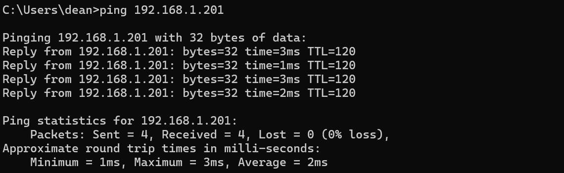
Type ping followed by the meter’s assigned IP address, then press Enter. The screenshot uses ping 192.168.1.201 for the EM133-XM. For the EM235 demonstration, use ping 192.168.1.203. At another site, substitute its approved address. Read the response lines and packet summary.
ping 192.168.1.201
The EM133-XM example shown below. Use the address assigned to your meter.
EM133-XM example, 7 November 2026: four echo requests and four replies, with zero packet loss. This confirms IP reachability at that time; it does not identify the meter or test Modbus. The current EM235 example uses a different address, 192.168.1.203. Open full-size imageInterpret the response carefully
Look for echo replies from the requested address. A message such as Destination host unreachable, even if it starts with Reply from another address, is not a successful reply from the meter.
A successful ping does not prove that TCP port 502 is available, that Modbus is responding, or that this is the intended meter. Continue with PAS communication and identity checks. A timeout means the echo test did not succeed; an ICMP filter can also prevent replies, so it is not proof that the meter is powered off.
Enter the network connection in PAS
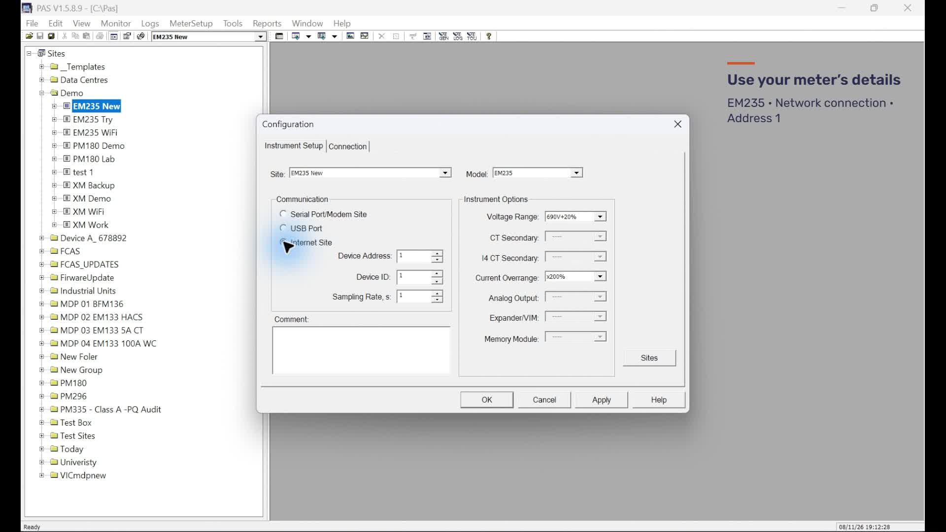
After creating the correct model’s site, choose Internet Site in Tools > Configuration. Enter the device address assigned to that meter. On Connection, enter its IP address, select the matching Modbus protocol and check Host Port.
Use port 502 for the dedicated direct Modbus TCP connection. A routed, VPN or APN arrangement may use another assigned destination port; use the network’s documented value. Do not change the meter’s IP merely to match the example.
Wait for answer and Retries control how PAS handles delayed or missing responses. Their values are site-dependent. First check the address, route, port and protocol; longer timeouts cannot correct a wrong destination. Detailed tuning is covered separately from this first connection exercise.
When finished with Command Prompt, type exit and press Enter to close that command session.
USB–RS-485 converter
Identify the converter’s current COM port before opening PAS. The PC’s COM number and the meter’s serial communication address are different settings.
Connect the converter first
Plug the USB–RS-485 converter into the PC before starting PAS. If it was connected after PAS opened and is missing from PAS’s port list, close PAS and reopen it with the converter connected. This sequence addresses the behaviour observed in the demonstration installation; it is not a claim that every Windows application behaves this way.
Read its COM number in Device Manager
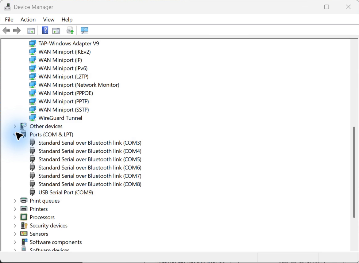
Select Windows Start, type Device Manager and open the result. Expand Ports (COM & LPT). Find the USB serial converter by its device name and note the COM number in brackets. Use the number displayed now, rather than assuming that a previous COM9 assignment still applies.
Device Manager from the 7 November 2026 PM296 demonstration. USB Serial Port (COM9) is separate from the Bluetooth ports above it. Read the number Windows assigns now; COM9 is this recorded example, not a required setting. Open full-size imageIf the converter is not identifiable
If Ports (COM & LPT) is absent or there is no identifiable converter entry, resolve detection or the converter’s driver before selecting a port in PAS. Do not choose an unrelated port or reassign numbers at random. A warning symbol on the converter also needs attention before this connection check can be considered complete.
Match the serial settings in PAS
After opening PAS and creating the correct model’s site, choose Tools > Configuration > Instrument Setup > Serial Port/Modem Site. Enter the meter’s configured serial address. Open Connection, select the current COM port in Device, and use Configure to set the baud rate and data format to match the meter.
Open Protocol and select the protocol used by the meter, such as Modbus RTU. The PM296 training example used 19,200 baud, but your meter’s actual settings govern. Confirm the address and parity/data format as well; the baud rate alone is not enough.
COM9, when assigned, is a port name on the PC. COM1 on a meter identifies a physical communication interface. A Modbus device address identifies the responding device on the serial link. These are separate values, and none can be inferred from another.
Recheck Device Manager when you change PC, converter or USB socket. Read the displayed assignment instead of memorising one COM number.
Before moving on
You know the intended connection settings and have recorded what the Windows check actually proves.
4. Create the site and confirm communication and identity
With PAS offline, choose Tools > Configuration. On Instrument Setup, select Sites, choose the demonstration folder, enter a short name and select New, then OK. Select the actual model and instrument options. Enter the connection settings from the matching connection path; a new site initially contains local defaults.
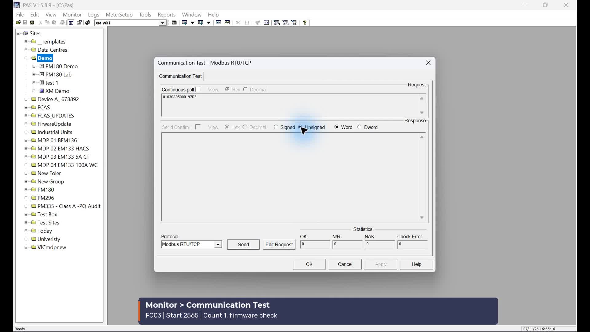
Select the intended site and go online. Open Monitor > Communication Test for a read-only check using a documented fixed value for that exact model, such as firmware or a serial-number field. Check the register address convention, format and expected interpretation before reading. A successful firmware read is useful evidence of communication, but firmware is not a unique identity.
Right-click the site and open Properties. Check the online model and serial number against the intended meter, then scroll through its information. Do this before CT scaling or other measurement changes. After identity is established, preserve the current settings using the backup lesson below.
A site name is a local label, not proof of meter identity. Offline Properties and setup screens can contain saved values. Confirm current information through a successful online read.
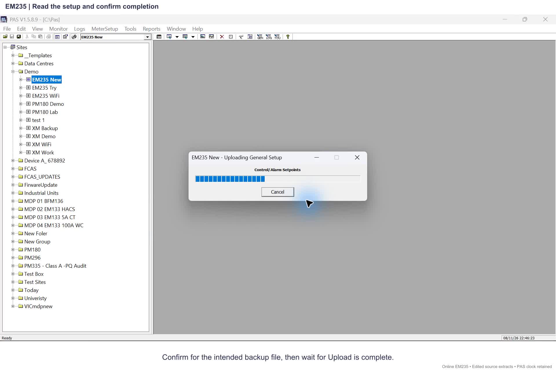
Upload Setups copies the connected meter’s settings into the selected site database. Preserve existing offline work first and keep a dated backup of the retrieved settings. Upload Logs is separate: it retrieves recorded history. Save As stores setup data locally; Send and Download Setups write to the meter. A successful connection is not a reason to send the defaults from a new site.
Recheck the selected site and its connection settings. For serial, confirm the actual COM number and match the meter’s address, baud rate, data format and protocol. For network access, confirm the assigned IP, host port and protocol. Record the error and test result before changing anything.
Do not change CT ratio to troubleshoot communications. Do not assume a changing voltage or current register is a unique identifier. The following EM133-XM recording shows a stable firmware read; its register choice must not be copied into another model without the corresponding guide.
Keep the site name short so the Site Tree leaves room for configuration and live monitoring.
If OK is outside the visible part of a dialog, press Enter only after confirming the active dialog and that its default action is the OK confirmation you intend. Do not use Enter blindly on a warning, Send, Delete or Reset dialog.
Learn the menu route first. Add Alt-key shortcuts after you can recognise the correct screen and selected meter.
EM133-XM recording only; starts with an established connection
Before moving on
A valid response and current online meter information identify the intended device. Ping or a firmware value alone is insufficient.
5. Back up the setup and duplicate the file
Preserve existing offline work first. After confirming the connected meter, use the backup lesson to retrieve its current setups into the intended site database, then keep a dated copy and a separate working duplicate.
Upload Setups retrieves configuration. Upload Logs retrieves recorded history. Keep these separate: a configuration copy is not a log archive.
The original setup copy and working duplicate are distinct, named and reopenable.
6. Understand online/offline settings, CT/VT and wiring
Use the saved copy to learn the difference between local editing and writing to a meter. Save As stores local setup data; Send and Download Setups write to the selected meter.
Before interpreting scaling or phase relationships, check the exact model, fitted measurement inputs, recorded CT/VT information and the applicable wiring drawing. If any of these is uncertain, preserve the readings and ask for the missing information. This page does not specify wiring connections or setting values.
Reading the example does not require changing a live meter. Follow the model-specific procedure and an authorised change scope before sending settings. Wiring work belongs to qualified personnel and the applicable installation instructions.
Optional EM133-XM CT-primary example. It is not a VT or wiring procedure for another model.
Before moving on
You can explain what remains local and what would change the meter. Any live change has an identified target and scope.
7. Interpret readings and keep the evidence
First state the model, the source of the display and whether you are viewing live readings or a saved record. A successful connection does not by itself establish correct measurement scaling, wiring or a completed event capture.
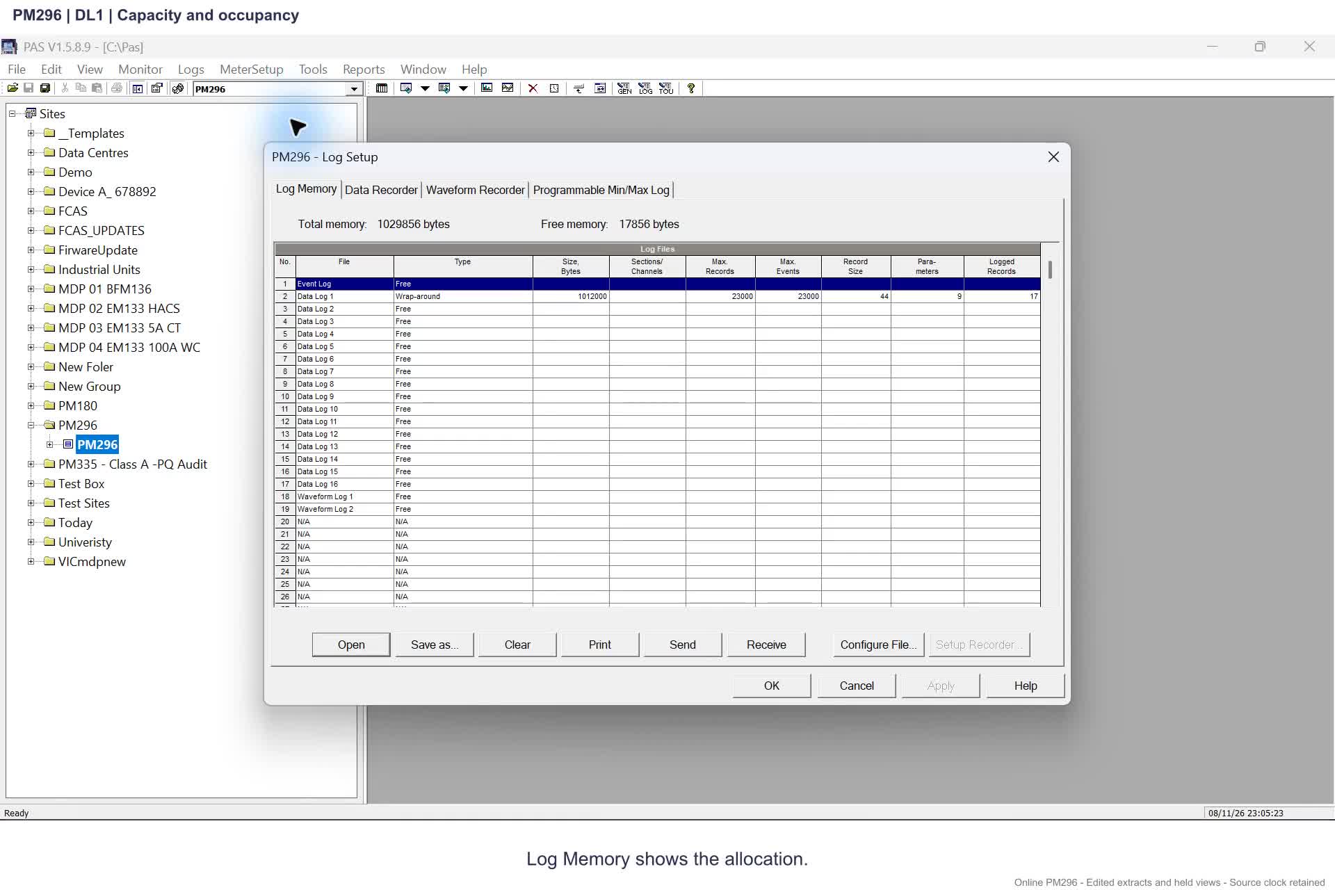
Use the energy lesson to understand quantities and compare recorded readings. For log or waveform work, open the matching model lesson and keep its offline/live boundary visible. Retain the original evidence before changing memory or configuration.
Existing offline PAS recordings and written explanations. These films do not show a newly captured event or a completed export.
Before moving on
You can describe the observation, its model and time context, and what has yet to be checked.
About the recordings
The menu, communications and waveform recordings were made for this training programme on 7–8 November 2026 and retain their stated offline or historical context. The installation film reuses an earlier SATEC capture with new narration, labelled separately. No vector-interpretation film has been selected.
Written guides have no play control. An unavailable film is not presented as playable.
BG0337 Rev.A2, printed/PDF page 10: Save As stores local setup data; Upload Setups retrieves settings; Send and Download Setups change meter settings. Pages 21–22: Upload Logs retrieves recorded history.

 1. Install or check PAS
 2. Find the Site Tree and the selected meter
 3. Choose serial or Ethernet and check Windows