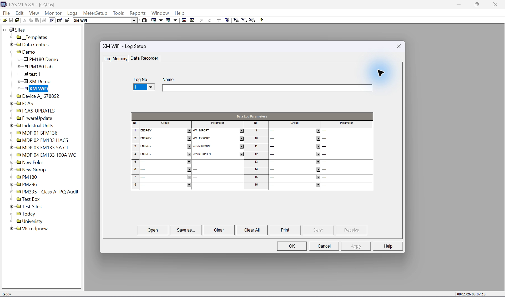
Data Log 1 is a conventional recorder. The family manual describes an energy-and-demand periodic default, but the selected site's current configuration is the authority for what it actually records.
Manufacturer source review complete; demonstration-specific verification and editorial acceptance pending.
Voice samples — audio only
Listen to the proposed delivery. The revised screen recording is pending; these samples do not replace the lesson video.
Charlotte · en-US · American
Voice sample for the revised Data Log 1 lesson. The new allocation-screen demonstration is not yet complete.
Start with Data Log one. The parameter list tells you what goes into each record. On the X M, you can select up to sixteen values. Now look at Log Memory and select Data Log one again. Number of Parameters is the width of the record. Number of Records is how many snapshots the file can keep. Those are two different limits. Before changing the allocation, upload your logs and open the saved file to check that the history is there.
Before you start
Use the intended EM133-XM site and verify its model, connection and firmware before treating settings as live.
Complete the existing Upload and verify your logs before changing memory lesson before any operation that can alter or remove retained records. Upload Setups and Upload Logs preserve different information.
Understand the documented default without assuming it is current
The EM13x manual describes fifteen-minute periodic Data Log 1 recording using a clock-linked Setpoint 1. Its example includes import/export energy, sliding demand and voltage-demand quantities.
The same manual permits changing both the recorded parameters and update rate. A site previously configured for another task may differ completely. Read the actual setup before describing the demonstration.
The Data Recorder tab defines the contents; the memory partition defines the permitted allocation. A report name helps identify the purpose but does not change the underlying measurement.
The XM datasheet allows up to 16 parameters/channels for interval recording. Check this file’s allocated parameter count and selected rows. Those values share one record; the file’s Number of Records and recording cadence determine how much history can be retained. After inspecting the fields, return to Log Memory and read this file’s allocation.
Choose the correct recorder
Open MeterSetup > Memory/Log > Data Recorder and select Log No. 1. Read the Name and each populated Group/Parameter row.
Keep the Site Tree visible and expand the selected site with + if needed; confirm the site and log number before proceeding.
Identify whether each selected value is cumulative energy, instantaneous power or a demand value. Record its units and import/export direction. Do not call every energy-related column interval consumption.
Inspect the corresponding Log Memory allocation. Stay within the supported parameter count for the exact unit and archive retained history before an allocation change.
Open MeterSetup > General Setup > Control/Alarm Setpoints. Inspect the existing row rather than overwriting Setpoint 1 because it appears in the factory example.
For the periodic lesson, MINUTE INTERVAL supplies the cadence and DATA LOG #1 identifies the destination. A trigger field alone is incomplete without the action. Review the full row, including delays and any existing application purpose.
Inspection
Question to answer
Trigger and interval
When should a record be requested?
Action
Does the action target Data Log 1?
Other setpoints
Can another row also record to the same file?
Readback and new records
Did the meter retain the intended setup and produce the expected timestamps?
A table makes individual timestamps and values explicit. A trend helps reveal changes across the selected time range. Neither view corrects a wrong quantity or missing records.
Retrieve the required history
Select the intended online site, choose Logs > Upload Logs, select the archive database and use Select Logs to include Data Log 1. Review From and To filters and allow the upload to complete.
Use File > Open, choose Access Database (*.mdb), select the saved archive and the relevant data-log table. Confirm its field names and first/last timestamps.
Use the Data Trend button in the data-log view. Select the intended Time Range and compare the graph with the underlying rows so that sparse or missing points are not mistaken for continuous measurement.
Check consecutive timestamps, expected spacing, units, field names and any gaps. Retain the configuration used for the archive so later viewers can identify the quantities.
Engineering example: a cumulative energy difference may support an energy-use calculation only when units/scaling, time boundaries, resets and rollover have been handled. A periodic instantaneous kW sample is not itself interval kWh. NEM data requirements are covered separately in the interval-selection lesson.
The written procedure is not evidence that a live setting was changed or that new records were generated. Check the selected device, firmware and current readback.
This lesson does not establish settlement suitability or measurement accuracy.
Check your understanding
Is the manual's fifteen-minute default proof of the current site setting?
Show answer
No. Receive/read the intended meter's configuration and inspect the uploaded records.
TBV1.1, PDF page 2, Event and Interval Data Recording
XM-specific datasheet lists up to 16 parameters/channels. Older family and unified-protocol tables list nine; confirm the selected model, firmware and PAS allocation before changing a file.
Revision and review details
Revision
Change and reason
Review / supersedes
20261108-draft-v1 8 November 2026
Added a detailed model-scoped log lesson with source references and learner checks.
Explain each log's purpose, PAS controls and interpretation without assigning invented factory roles.