
RPM072 + RDM172 · TECHNICIAN GUIDE
How do I check an RPM072 remote display connection?
Identify the connector first. Check the meter and display nameplates, cable markings and both connector ends, then use the matching diagram. The pin and terminal numbers are different.
Two conditional arrangements are documented: a dedicated 15-pin display connection and a separate seven-terminal RDM172 connection. Do not combine them.
Sources and numerical wiring claims verified against the included manuals on 6 November 2026.
Applies to
- RPM072
- RDM172
References: PM172 IOM BG0399 Rev A9 for the dedicated 15-pin display connection, and RDM172 Quick Guide BG0324 Rev A2 for the separate seven-terminal connection. Use the matching diagram only; the pin and terminal numbers are different.
Listed under PM17x remote display. Family membership is not a compatibility claim.
Identify the connector first
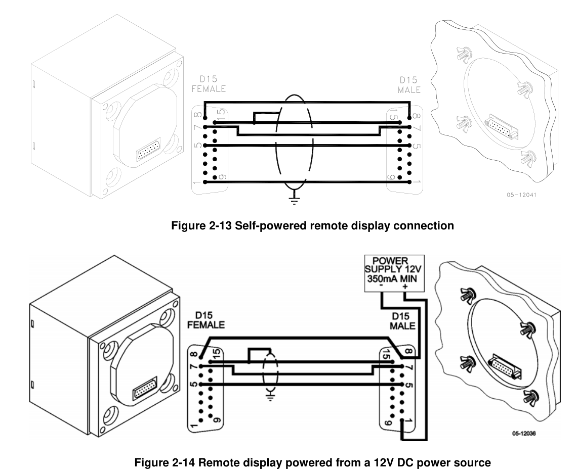
Figure 2-13 meter-powered and Figure 2-14 externally powered reference diagrams. Pin table on p15.
PM172 Installation and Operation Manual · BG0399 Rev A9 · p16
Open manual page
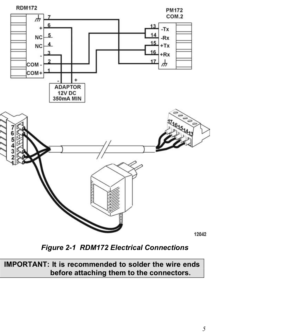
Figure 2-1 seven-terminal connection.
RDM172 Quick Guide · BG0324 Rev A2 · printed p5 / PDF p6
Open manual page
Use the matching diagram. The pin and terminal numbers are different.
Isolate before connector checks
- A qualified electrician follows the site isolation procedure.
- Isolate the relevant power sources before touching connectors.
- Disconnect both cable ends before continuity checks.
- Do not open a CT secondary while its primary is energised.
VERIFIED — PM172 IOM · BG0399 Rev A9, p. 2; checked 6 November 2026. Open manual page
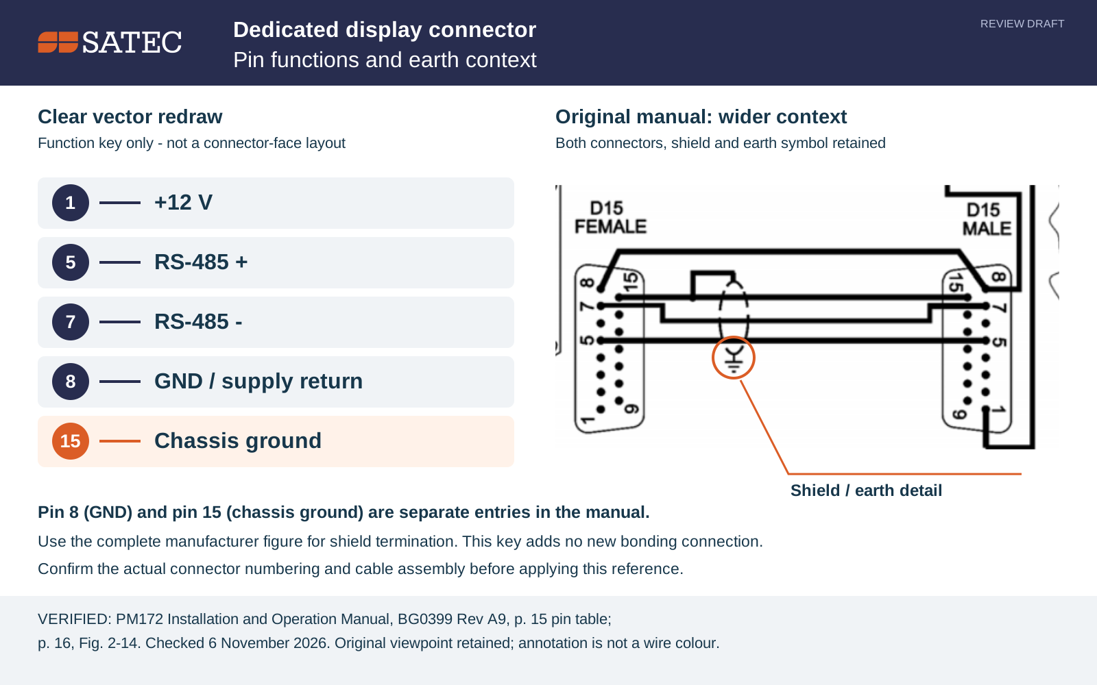
Dedicated 15-pin connection: read each numbered pin
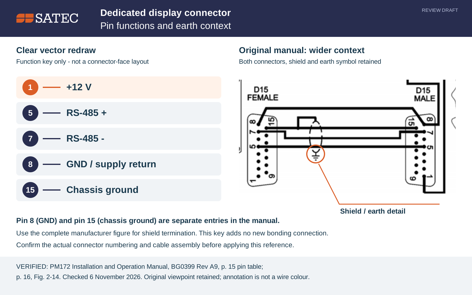
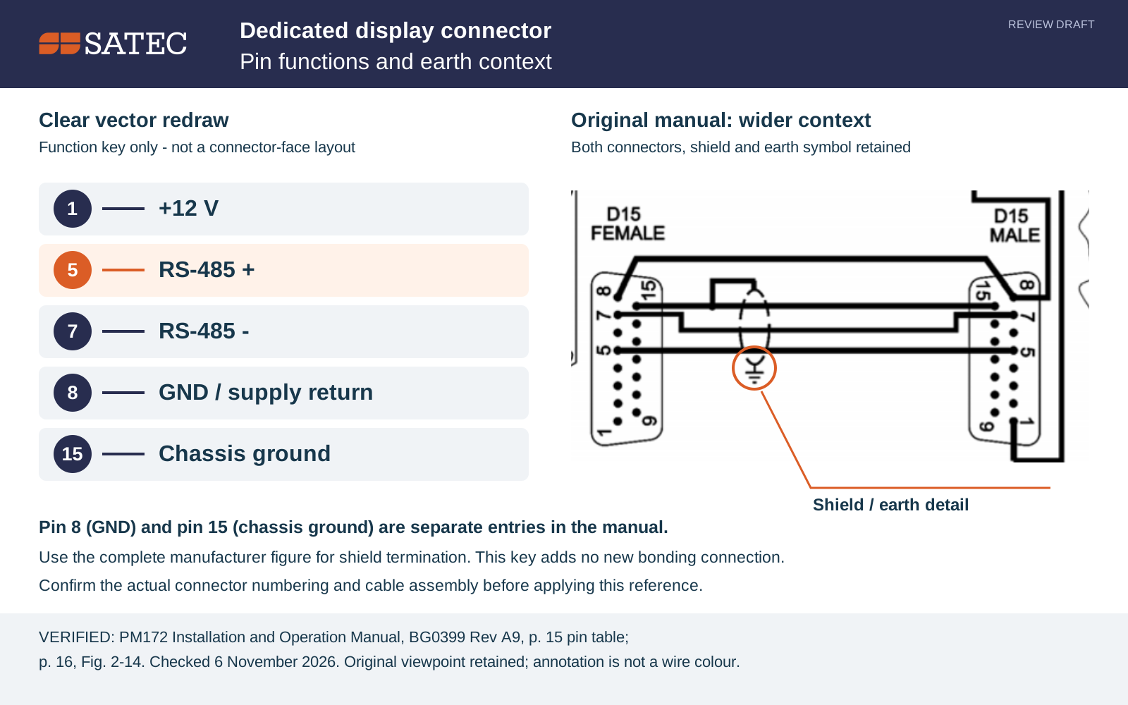
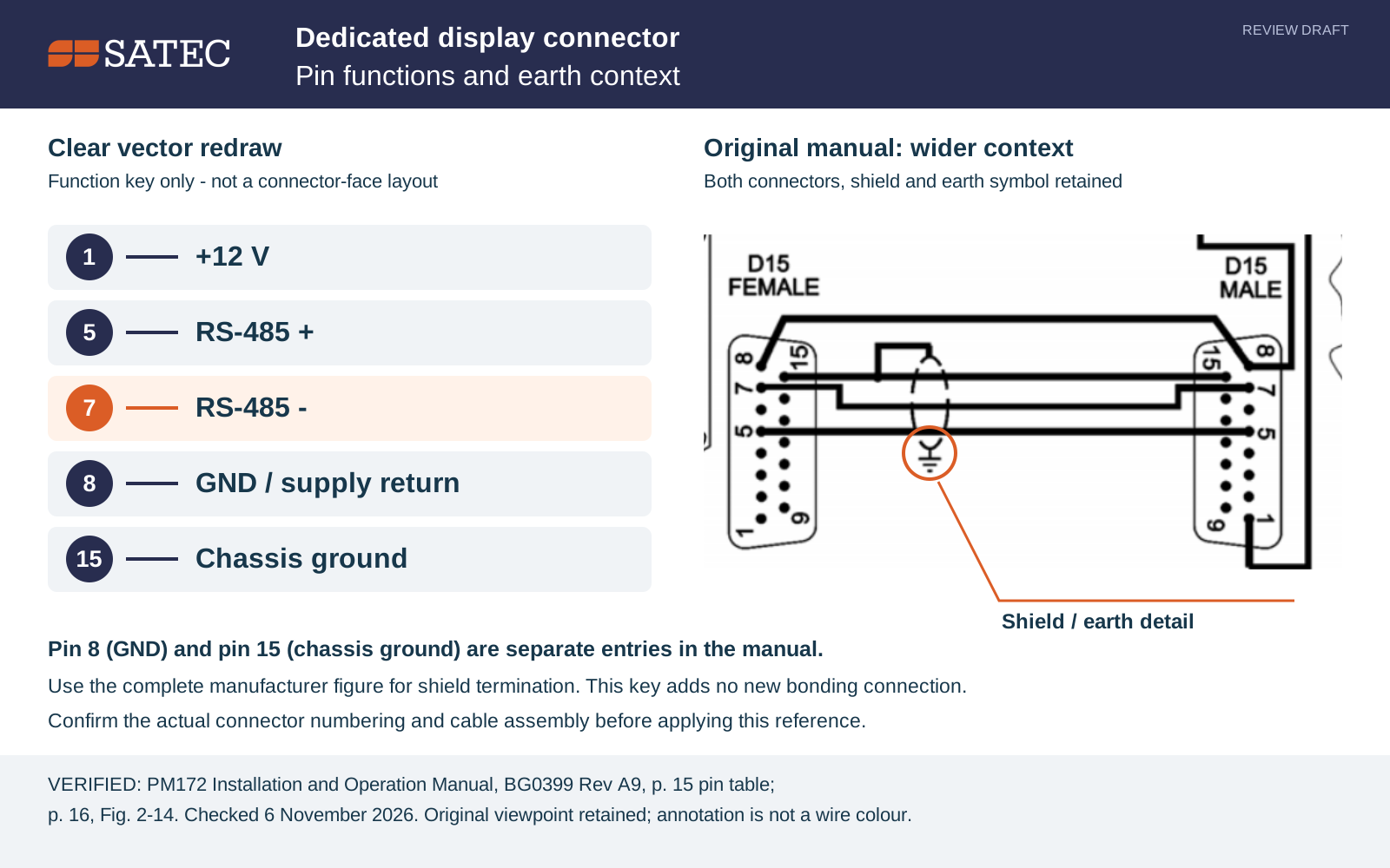
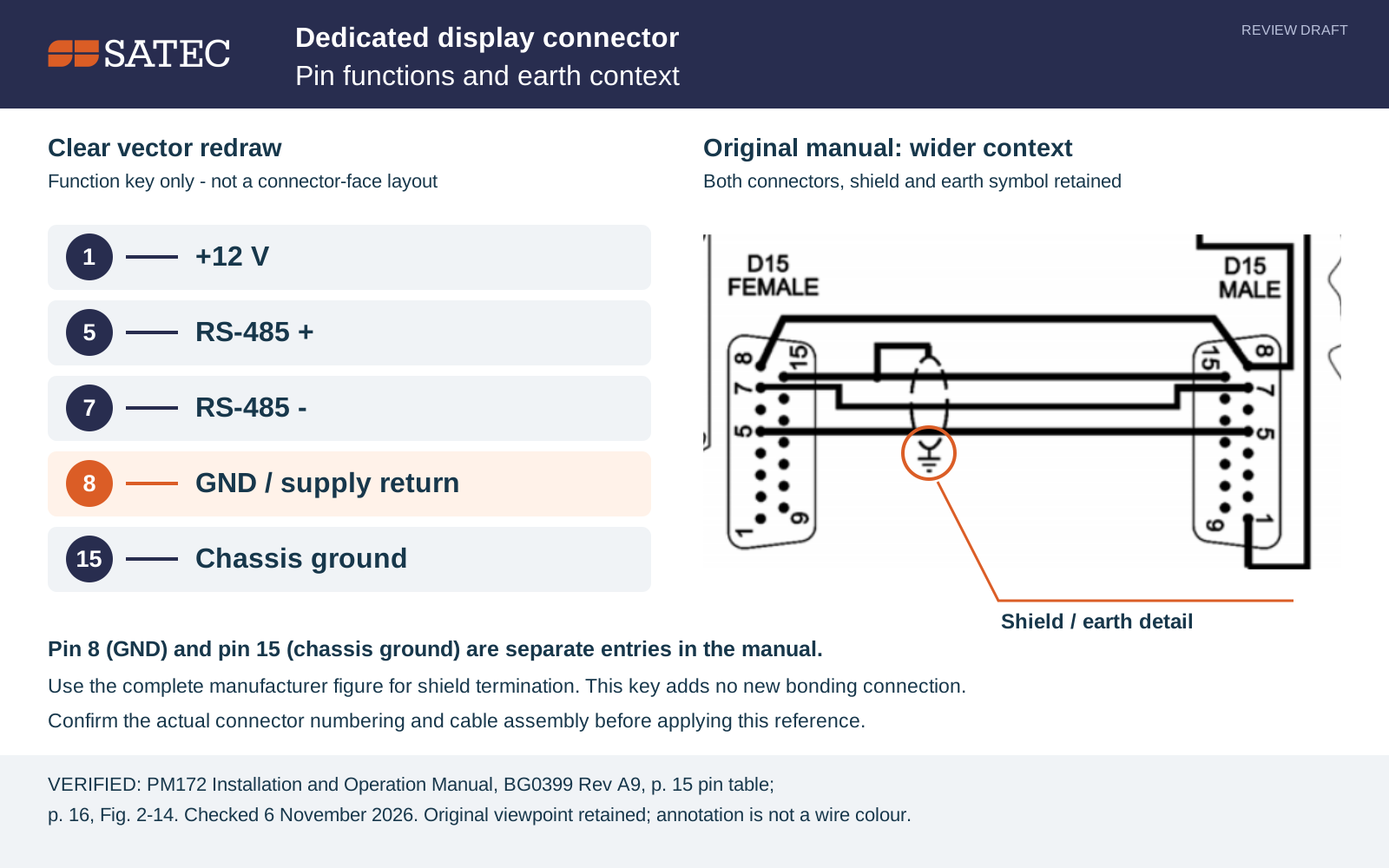
Dedicated 15-pin reference only. Locate the number on the actual connector. Keep the manufacturer’s viewing direction.
| Pin | Function | Function drawing |
|---|---|---|
| 1 | +12 V | Pin 1 drawing |
| 5 | RS-485 + | Pin 5 drawing |
| 7 | RS-485 − | Pin 7 drawing |
| 8 | GND / supply return | Pin 8 drawing |
| 15 | Chassis ground | Pin 15 drawing |
VERIFIED — PM172 IOM · BG0399 Rev A9, p. 15 pin table; p. 16 connector figure; checked 6 November 2026. Open manual page
Keep the manufacturer’s view. Confirm numbering on the actual connector; do not infer the solder-side or mating-face view. The redrawn key shows functions, not a physical connector face.
The wider manual view retains the shield and earth connection.
Figures 2-13 and 2-14 as published, shown again beside the pin table so the shield and earth connection stays in view.
PM172 Installation and Operation Manual · BG0399 Rev A9 · p16
Open manual page
Meter-powered display connection
For the documented dedicated connection, the meter can power the display over a cable up to 3 m.
VERIFIED — PM172 IOM · BG0399 Rev A9, p. 15 text; p. 16, Fig. 2-13; checked 6 November 2026. Open manual page
Match the cable assembly and connector. Meter control power is a separate circuit.
Trace the separate display supply
Above 3 m: the documented arrangement uses 12 V DC with at least 350 mA capacity.
- Supply + → display pin 1
- Supply − → display pin 8
- Meter pin 1: unconnected
VERIFIED — PM172 IOM · BG0399 Rev A9, p. 16, Fig. 2-14; checked 6 November 2026. Open manual page
Do not parallel the supplies. This figure is conditional on the installed arrangement.
Seven-terminal version: separate reference
Use this only if the display has the matching seven-terminal connection.
- Display 1 → linked COM2 15/16
- Display 2 → linked COM2 13/14
- Display 7 → COM2 17
- External supply + → display 6
- External supply − → display 3
- Display 4 and 5: NC
12 V DC, ±15%; minimum 350 mA.
VERIFIED — RDM172 Quick Guide · BG0324 Rev A2, printed p. 5 / PDF p. 6, Fig. 2-1; introductory supply precautions; checked 6 November 2026. Open manual page
Connection walkthrough
Connection walkthrough
Duration 0:53, measured from the file.
Captions are included in the video. A separate subtitle file is also available.
Transcript
For the matching 15 pin display connection, the manual identifies pin 1 as positive 12 volts, pin 5 as communications plus, pin 7 as communications minus, and pin 8 as the supply return. Pin 15 is chassis ground, follow the numbered connectors and the complete manufacturer drawing. Do not infer the connector viewing direction. For this documented connection, a cable up to three metres can carry display power from the meter. Longer connections use the separate 12-volt supply arrangement with a minimum capacity of 350 milliamps. The supply feeds display pins one and eight. meter pin one is not connected in that arrangement. Do not parallel the two supplies.
Record results before selecting the next test
Record
- Record connector type, cable marking and length.
- Record the supply source, polarity and check result.
- Record required conductor continuity and any unintended shorts.
- Record the exact display message and existing communications settings.
- Return photographs and results for a controlled diagnosis.
A blank display or a connection error does not identify a failed component.
VERIFIED — PM172 IOM · BG0399 Rev A9, pp. 15–16, 32–33; checked 6 November 2026. Open manual page
Real 3D connector geometry has not been established. Manual drawings have been retained.
Manuals and page references
Manual links open the cited page. Printed and PDF page numbers are shown where they differ.
| ID | Document / revision | Pages | Evidence used |
|---|---|---|---|
| M1 | PM172 Installation and Operation Manual BG0399 Rev A9 Pin table, p15 Connection figures, p16 | 2; 15–16; 32–33 | Safety, pin table, connection figures 2-13 and 2-14, troubleshooting references |
| M2 | RDM172 Quick Guide BG0324 Rev A2 Terminal wiring, printed p5 / PDF p6 | printed 5 / PDF 6 | Seven-terminal wiring, Figure 2-1; supply precautions |
Technical release note
The checking guide retains the two conditional connector arrangements. The redrawn key shows functions, not a physical connector face. Function redraw is not a connector-face geometry or new earthing design.
If it still does not work
Return photographs and results for a controlled diagnosis: connector type, cable marking and length, supply source and polarity, continuity results, and the exact display message with the existing communications settings.