
BFM136 + BFM-II · TECHNICIAN GUIDE
How do I address multiple BFM meters on RS-485 or Ethernet?
On RS-485, give each BFM a non-overlapping block of submeter addresses. On native Ethernet, give each meter a suitable unique IP address and confirm the client’s submeter selection.
A different base address alone is not enough. A BFM represents several logical submeters, and their addresses must fit into the network plan.
Product statements checked against the manufacturer manuals listed below on 6 November 2026. Examples are illustrative, not settings for your site.
Applies to
- BFM136
- BFM-II
This package covers the named BFM136 and BFM-II manuals; check the installed model and firmware before applying it.
Listed under BFM branch feeder monitors. Family membership is not a compatibility claim.
Choose the level of detail
Short overview
Duration 0:30, measured from the file.
The key distinction: logical address blocks on serial networks and IP settings on Ethernet.
Transcript
Adding another BFM to RS-485. Reserve a non-overlapping block of submeter addresses, not just a different base address. Match serial settings. Check labelled polarity, shielding and termination against the model's manual. On Ethernet, use a unique IP address for each meter. Test devices separately, then rebuild the network and verify every configured submeter.
Walkthrough
Duration 1:15, measured from the file.
Build an address schedule, inspect the selected interface and test devices individually.
Transcript
A BFM can expose several logical submeters. On a shared RS-485 network, different base addresses are not enough. The complete submeter address blocks must not overlap. For example, three meters configured only for submeters 1 through 12 can use bases 1, 13 and 25. This is an example, not a site setting. Include totalisers and gaps. The highest configured submeter number determines the span you reserve. Record the existing protocol. baud rate. Data bits and parity. Match the master and every device. Check plus, minus and shield against the correct manual drawing. Follow its earthing and termination arrangement. Do not infer polarity from another manufacturer's A and B labels. For native Ethernet, each meter needs a unique IP address on the local network. The subnet mask and gateway may be shared. Confirm how your software selects the intended submeter. A serial gateway also needs its own routing configuration. Use qualified personnel and the site isolation procedure for physical wiring checks. Test one device at a time, then add devices back. Verify every configured submeter and record timeouts or errors. A failed response alone does not prove a faulty meter.
Review videos served from this preview. YouTube publication links will be added after release.
Check in this order
Identify every meter and connection
Record the model, serial number, firmware, fitted communications port and controller. Save the existing configuration. Distinguish a serial bus, direct Ethernet and a gateway feeding downstream serial devices.
List the complete submeter allocation
Record the base address and highest configured submeter index, including totalisers. Reserve the span through that index, even if it contains gaps. Check it against every other device on the serial bus.
S1 pp20–21; S2 pp6–7; S3 p41; S4 pp5–6.
Match the supported serial format
Confirm protocol, baud rate, data bits and parity at the meter and controller. The documented serial default is Modbus RTU, 19200 baud and 8 bits with no parity. Read the installed settings before changing them. Confirm controller stop-bit requirements against the actual meter interface; the cited manuals do not give an explicit stop-bit setting.
S1 p34, pp38–39; S3 pp38, 56, 65–66. A 7-bit format must not be used with Modbus RTU.
Check wiring against the fitted port
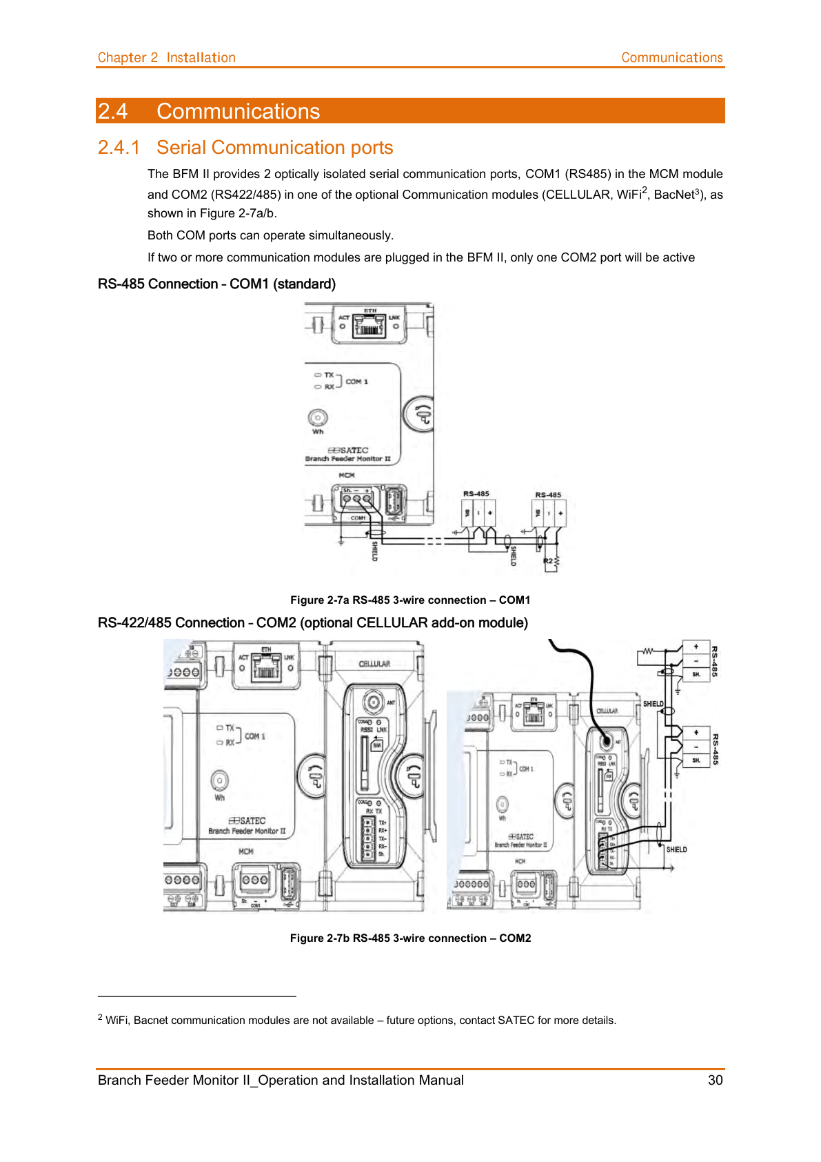
Identify the actual positive, negative and shield terminals. Follow the applicable manual drawing, including earth connections and termination. Do not infer polarity from A/B lettering alone. Arrange any wiring work under the site’s isolation procedure.
S1 p16; S3 p30. The BFM136 and BFM-II drawings are separate references.
Test separately, then rebuild the network
With an agreed test arrangement, read a known measurement from each intended submeter individually. Record the request and response. Reconnect the network and repeat the same reads. A flashing LED or a timeout alone does not establish the cause of a fault.
A configuration write can affect the complete BFM. Communication-port changes are addressed through the device base address. Begin with reads and recorded settings. S2 p7; S4 p6.
Plan the serial address blocks
The planning span ends at base + highest configured submeter index − 1. This reserves gaps; it does not mean every address in the span will respond.
| Device label | Base address | Highest configured submeter index | Reserved span |
|---|---|---|---|
| BFM A | 1 | 12 | 1–12 |
| BFM B | 13 | 12 | 13–24 |
| BFM C | 25 | 12 | 25–36 |
Interactive planner: edit the values to check spans and overlaps. It needs JavaScript; the worked example above shows the same arithmetic.
Optional advisory only: when the eXpertPower client is used, address 99 is reserved on the Ethernet port. This is not a general ban on serial address 99. Do not use this serial planner to infer native TCP Unit-ID behaviour.
Mapping and address range verified: S1 pp20–21; S2 pp6–7; S3 p41; S4 pp5–6. Allowed Modbus address range: 1–247. The planner checks arithmetic and overlap, not model capacity or firmware capability. Confirm the highest index is supported by the installed model.
Example only: with exactly SM1–SM12 configured on each device and no higher submeter, bases 1, 13 and 25 reserve 1–12, 13–24 and 25–36. Extra totalisers can extend those spans.
Keep the manual drawing in view
These are source-manual extracts, including earth symbols. Open the full page to see the original context. Enlarging the original improves readability but cannot add detail absent from the source.
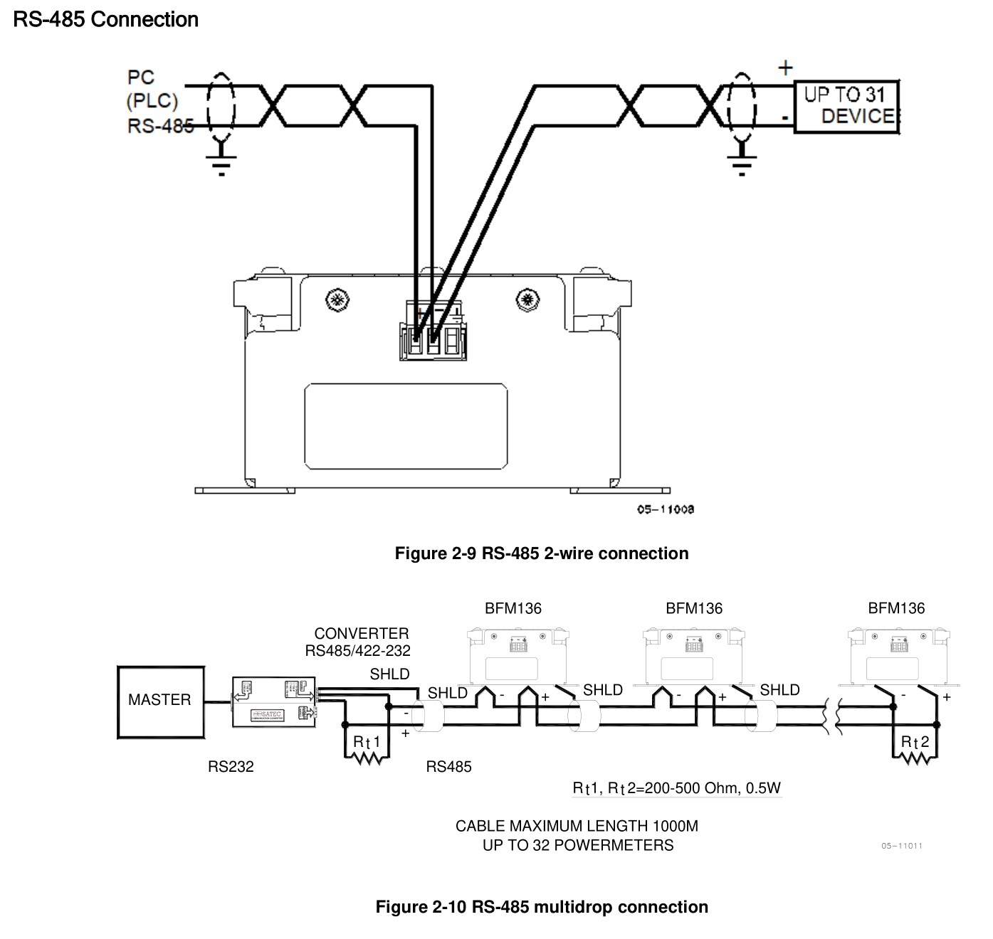
Figures 2-9 and 2-10. Terminal labels +, − and SHLD. The multidrop figure states Rt1/Rt2: 200–500 Ω, 0.5 W under its illustrated conditions. Check the actual converter and topology; do not transfer this value to another model.
BFM136 Installation and Operation Manual · BG0394 Rev A11 · p16
Open manual page · Full page image
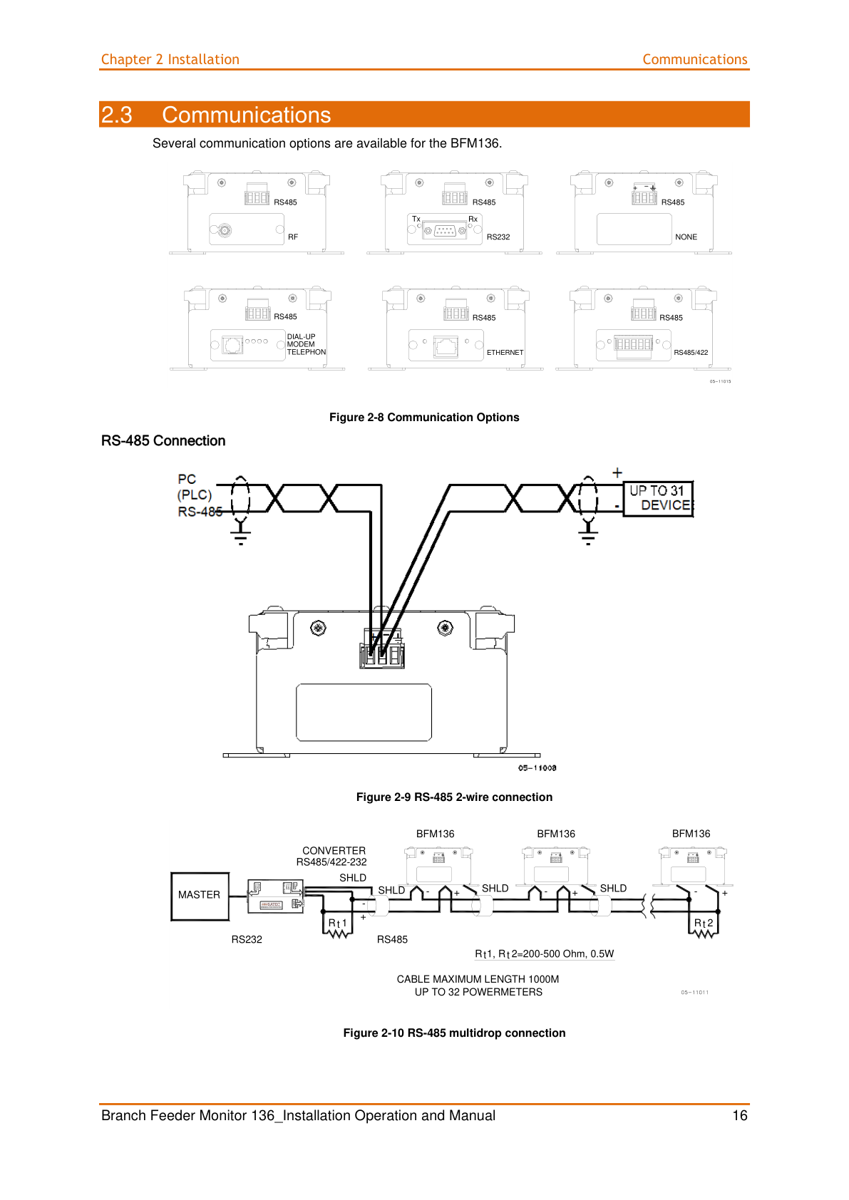
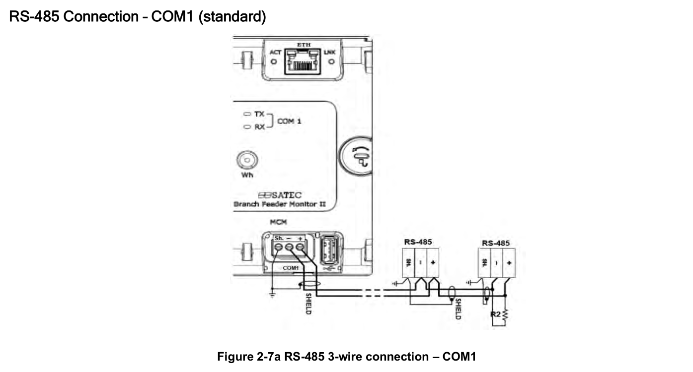
Figure 2-7a, standard COM1. Illustrated terminal order: Sh., −, +. Keep the shield identification; do not relabel it as signal-common GND. The figure labels end resistor R2 without a value. Optional COM2 has a separate drawing on the full page.
BFM II EM and DFR Operation and Installation Manual · BG0588 Rev A12 · p30
Open manual page · Full page image
Ethernet uses a different address plan
Direct Ethernet to each meter
Assign a suitable unique IP address to every meter on the common LAN. Use the subnet mask and gateway specified by the network owner; those values may be shared.
Use the intended Modbus TCP endpoint. The manuals list TCP service port 502. Confirm the installed firmware and client’s submeter selection before relying on Unit-ID behaviour.
S1 p34, pp38–39; S2 p53; S3 pp38, 57, 65–67; S4 p74.
Ethernet-to-serial gateway
The controller reaches the gateway’s network endpoint. The gateway then routes requests to downstream serial devices using its own configuration.
Document the gateway model and routing rules, then check the downstream BFM blocks and serial format. A reachable gateway IP does not prove that the intended submeter is replying.
Architecture check: use the installed gateway’s own manual. No gateway mapping is asserted by this package.
Do not connect several meters using the same factory IP. Record the network owner’s assigned addresses before joining them to the LAN.
Record what the test actually proves
Field checklist
- Model, serial number, firmware and physical port recorded.
- Base address and full configured submeter span checked.
- Master and meter protocol and serial format match.
- Polarity, shield, earth and termination checked against the applicable drawing.
- Ethernet endpoint and client submeter selection confirmed, if used.
- Individual and combined-network read results recorded.
Manuals and page references
VERIFIED against the local manufacturer manuals on 6 November 2026. Printed page numbers match PDF page numbers in these copies.
| ID | Document / revision | Pages | Evidence used |
|---|---|---|---|
| S1 | BFM136 Installation and Operation Manual BG0394 Rev. A11 | 16; 20–21; 34; 38–39; 41 | RS-485 drawings, submeter allocation, serial and network setup |
| S2 | BFM136/036 Modbus Communications Protocol Reference Guide BG0395 Rev. A8 | 6–7; 52–53 | Address range, base address, shared setup and network service |
| S3 | BFM II EM and DFR Operation and Installation Manual BG0588 Rev. A12 | 30–31; 38; 41; 56–57; 65–67 | Port identification, drawings, submeter allocation and communications |
| S4 | BFM-II Modbus Communications Protocol Reference Guide BG0589 Rev. A12 | 5–6; 73–74 | Address range, base address, communications and network setup |
Technical release note
The BFM-II manuals disagree on factory submeter allocation and maximum address occupancy, and contain differing descriptions of native Ethernet address handling. This guide does not prescribe those disputed defaults or a TCP Unit-ID mapping. Confirm the installed configuration and client behaviour before release for a specific site.
No explicit stop-bit value was found in the cited manuals. The calculator is an arithmetic planning aid and does not configure equipment.
If it still does not work
Send the completed inventory, clear nameplate and terminal photographs, a simple topology sketch, exported communications settings, controller or gateway model, and the exact failed request or error.
Include which devices respond when isolated and what changes when the complete network is connected. Record observations without declaring a duplicate address or failed meter until the evidence supports it.