
ETC II + ETC ONE PLUS · TECHNICIAN GUIDE
How do I connect and configure a SATEC ETC gateway?
Identify the exact gateway and prove a downstream meter before integrating the full upstream system. For pass-through operation, prove a client read through the gateway. For an ETC II Data Server, also verify that its cached exchange contains a successful, fresh meter response.
Start with the model label, firmware and intended data path. ETC II forwarding and Data Server services can coexist; ETC ONE PLUS has a different setup and forwarding scope.
No installed gateway has been tested for this guide. Documentary verification does not establish the configuration or condition of an installed device.
Applies to
- ETC II
- ETC ONE PLUS
ETC II (BG0594 Rev. A5): transparent gateway and configured Data Server can coexist. ETC ONE PLUS (BG0596 Rev. A2): documented pass-through branch; firmware and model conflicts unresolved. ETC2002 and other ETC One variants need their own confirmed documentation.
Listed under ETC gateways. Family membership is not a compatibility claim.
Identify the product before changing settings
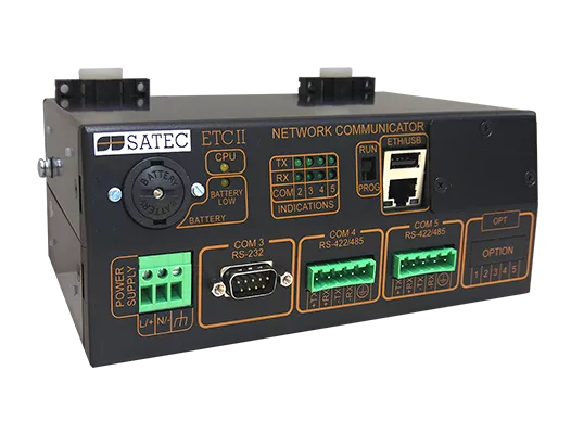
ETC II
Transparent Gateway + Data Server
Use the ETC II procedure for the exact fitted ports and firmware. COM4 and optional COM5 serve downstream serial networks. The embedded Data Server can acquire and store meter data separately from transparent forwarding.
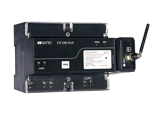
ETC ONE PLUS
Pass-Through Procedure
This branch uses the manual whose cover says ETC ONE PLUS. It documents COM1 as the downstream serial master and Ethernet or a fitted cellular module upstream. It does not establish an ETC II-style generic cached Data Server.
Select a photograph to enlarge it. Product photographs show example configurations; an antenna in a photograph does not establish the fitted module or current cellular compatibility. The nameplate, options and firmware determine which instructions apply. ETC2002 and other ETC One variants need their own confirmed documentation.
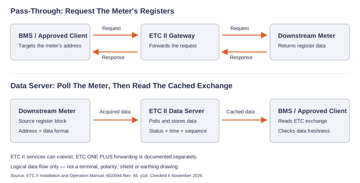
Logical explanation based on ETC II IOM p18. It is not a physical wiring diagram.
Prepare a small, traceable test
Record the existing configuration before an authorised change. This guide proposes a staged commissioning method; it does not diagnose a fault from a model name, a ping response or a flashing LED.
Record the actual equipment
Capture the gateway nameplate, supply variant, serial number, firmware, fitted modules and terminal labels. List each meter model, communication address, protocol, baud rate and framing. Confirm stop bits from the exact product and firmware documentation; the framing labels in these manuals do not establish a universal stop-bit count.
Separate the address types
Record the gateway's own configuration address, every downstream meter address, the gateway's Ethernet IP and any downstream Ethernet device IP. For Data Server operation, add the source meter register and destination ETC exchange address. These are different identifiers.
Preserve the setup
In PAS, select the correct site and use Upload Setups to read device settings into the site database. Save a dated copy. Send and Download Setups write to the device; they are not backup commands.
Prove a known meter read
Use the exact meter's protocol guide to select a small readable register block with known type and scaling. Prove it with an approved local client. Return the serial network to its normal master arrangement before testing through the gateway.
Inspect the physical installation
Qualified personnel should isolate supplies before installation or wiring work. Check the actual supply label, serial polarity, shield, earth and termination against the model-specific drawing and site design. Keep power terminals separate from communication terminals.
Backup direction: ETC II IOM p33; ETC ONE PLUS IOM p24. Supply and installation: respective IOM p9 and p9. Staged tests and recording are engineering recommendations, not a manufacturer acceptance threshold.
ETC II: configure the shared gateway path
ETC II · BG0594 Rev. A5
Create or select the PAS site
Open Tools → Configuration → Sites. Select model ETC II under Instrument Setup. Use the actual ETC configuration address. For an Ethernet connection, select Internet Site → Connection and enter the assigned IP. This manual's PAS label is Modbus RTU for Modbus/TCP; confirm the label in your PAS version. It does not authorise substituting a raw serial tunnel.
Read the serial port setup
Open Meter Setup → Communications Setup → Serial Ports Setup. Select the physical downstream port. COM4 must be in master mode when serving downstream meters; COM5 is documented as factory-set master. Match the connected devices' protocol and serial format.
Set the approved Ethernet values
Open Communications Setup → Network Setup. Use the site's assigned IP, subnet mask and default gateway. The documented Modbus/TCP service is TCP 502. Check for duplicate IPs before connecting to a shared LAN. Changing network settings restarts networking and can disconnect the current session.
Check the routing path
Open Meter Setup → ETC II Setup. Read the ETC own address and gateway address range. In Device Routing Table, associate each meter address with its actual COM4, COM5 or Ethernet destination; enter the downstream IP where applicable. Enable Routing Table in Gateway Options to make it effective. Ethernet slaves require the table. Explicit routing is documented from firmware V21.5.4; confirm installed firmware first.
PAS site: pp30–31; serial roles: p14; serial setup: p37; network: pp38–39; routing: p17 and pp43–44. Numeric claims verified against these pages on 6 November 2026.
Do not assume every meter address reaches the same serial port. With routing disabled, implicit rules depend on how COM4 and COM5 are used. The ETC's own address is reserved for its configuration and data. This ETC II routing table selects a port or IP; it does not document arbitrary translation to a different downstream slave address.
ETC II Branch A: verify transparent forwarding
The upstream client requests the downstream meter's registers through the ETC. The gateway forwards the request and returns the meter's response.
Use one approved client
Target the actual ETC IP and Modbus/TCP service. Select the intended downstream meter address in the client. Use the same known-valid source register, type and scaling established by the local test.
Check the complete response
Confirm the expected meter data and record any exception or timeout. Reading the ETC's own configuration proves access to the gateway only; it does not prove that the downstream meter can be reached.
Build out the network
Repeat the read for each meter before integrating the full BMS or cloud polling load. Record repeated responses over an agreed observation period. A repeatability threshold depends on the site; none is invented here.
Forwarding behaviour: ETC II IOM p18. Proposed test sequence is engineering guidance. No automatic polling exchange is required solely for this forwarding path.
ETC II Branch B: configure and verify the Data Server
The ETC acquires selected source registers and places them in its own exchange memory. The BMS reads the mapped ETC exchange, including its quality and time information.
Inspect global Data Server options
In Meter Setup → ETC II Setup, inspect Data Server Operations, continuous or interval polling, and logging. Global operations and each intended exchange must be enabled for acquisition. Logging is a separate choice from real-time polling.
Define each read exchange
Open Real-Time Data Exchanges. Set the actual meter address, source meter start register and contiguous block size from that meter's protocol guide. Select Polling Enabled. PAS displays the corresponding ETC exchange start address. Record that mapping for the upstream integrator.
Preserve the existing map
Exchange locations depend on the sizes of preceding exchanges. Changing the setup can move later locations and lose previously acquired data. Review the BMS map before an authorised change. Real-time, status and write exchanges sharing an exchange number also share the device address.
Read the cached result at the ETC address
Use the ETC's own configuration/data address and mapped exchange location. Decode the record status, time and sequence before the payload. Compare the data with the known meter result, then confirm that the timestamp and sequence refresh with the configured polling.
| Offset from exchange start | Meaning | Acceptance check |
|---|---|---|
+0, +1 | Record status, UINT32 | Decode the response. Zero is no data; minus one is corrupted. Other values can encode a function or exception response, so nonzero alone is not a pass. |
+2, +3 | Record time, UINT32 | Confirm freshness using the configured acquisition interval and correct clock. |
+4, +5 | Record sequence, UINT32 | Confirm change as new records are acquired; handle wrap using the protocol guide. |
+6 onwards | Acquired meter registers | Apply the original meter's data types, word order, units and scaling. |
Configuration: ETC II IOM pp48–49. Layout, movement and status: ETC II Modbus Guide, BG0595 Rev. A2, pp8–9 and p12. Register notation: p5. Numeric claims verified on 6 November 2026.
Keep the first communications test read-only. RTC synchronisation writes the meter clock; status Auto Reset can clear a meter register; write exchanges change downstream data. These are separate functions, not necessary proof of a successful read. Confirm the driver's zero-based versus holding-register notation before entering a register address. ETC II IOM pp49–51.
ETC ONE PLUS: use the separate forwarding procedure
ETC ONE PLUS · BG0596 Rev. A2
This manual documents pass-through Modbus forwarding. Do not apply the ETC II Data Server tabs, COM4/COM5 routing or exchange-memory map to ETC ONE PLUS.
Confirm the variant and mode
Identify the exact module and firmware. Normal operation uses COM1 as the downstream serial master. Programming mode makes it a service/slave port and disables forwarding. Confirm PROG is off for the forwarding test; obtain the firmware-specific procedure if it remains on.
Create the PAS site and preserve settings
Use Tools → Configuration → Sites, model ETC ONE PLUS. Use the actual gateway address. Read the existing device configuration using Upload Setups before an authorised write.
Verify COM1 and the Ethernet module
Match the meter's Modbus RTU and serial settings. For a fitted Ethernet module, use Communication Setup → Serial Ports Setup → COM2 to select Ethernet, then Network Setup for the assigned IP, subnet, gateway and service port. The documented inbound Modbus/TCP service uses TCP 502.
Confirm forwarding applicability
The manual describes a predefined forwarding table. Its stated address range conflicts with a wiring example. Have the product specialist confirm usable downstream addresses for the installed firmware before adopting a full address plan. Do not assume the table is freely editable.
Prove the meter through the gateway
Use one approved Modbus client, the gateway IP/service and intended meter address. Read the documented meter register, confirm its value and repeat for each remaining meter. Add the BMS or cloud client after the forwarding path works.
Modes: p14; serial settings: p16; Ethernet: pp17–18; PAS: pp22–24; predefined table: p27. Numeric claims verified on 6 November 2026.
Confirm the exact variant where the manual conflicts. The supplied manual has conflicting instructions around downstream address limits, service-mode address semantics, supply range and how to leave programming mode. Obtain confirmation for the installed firmware instead of selecting a disputed default or power-cycle instruction. Cellular and cloud endpoints require current module and service information.
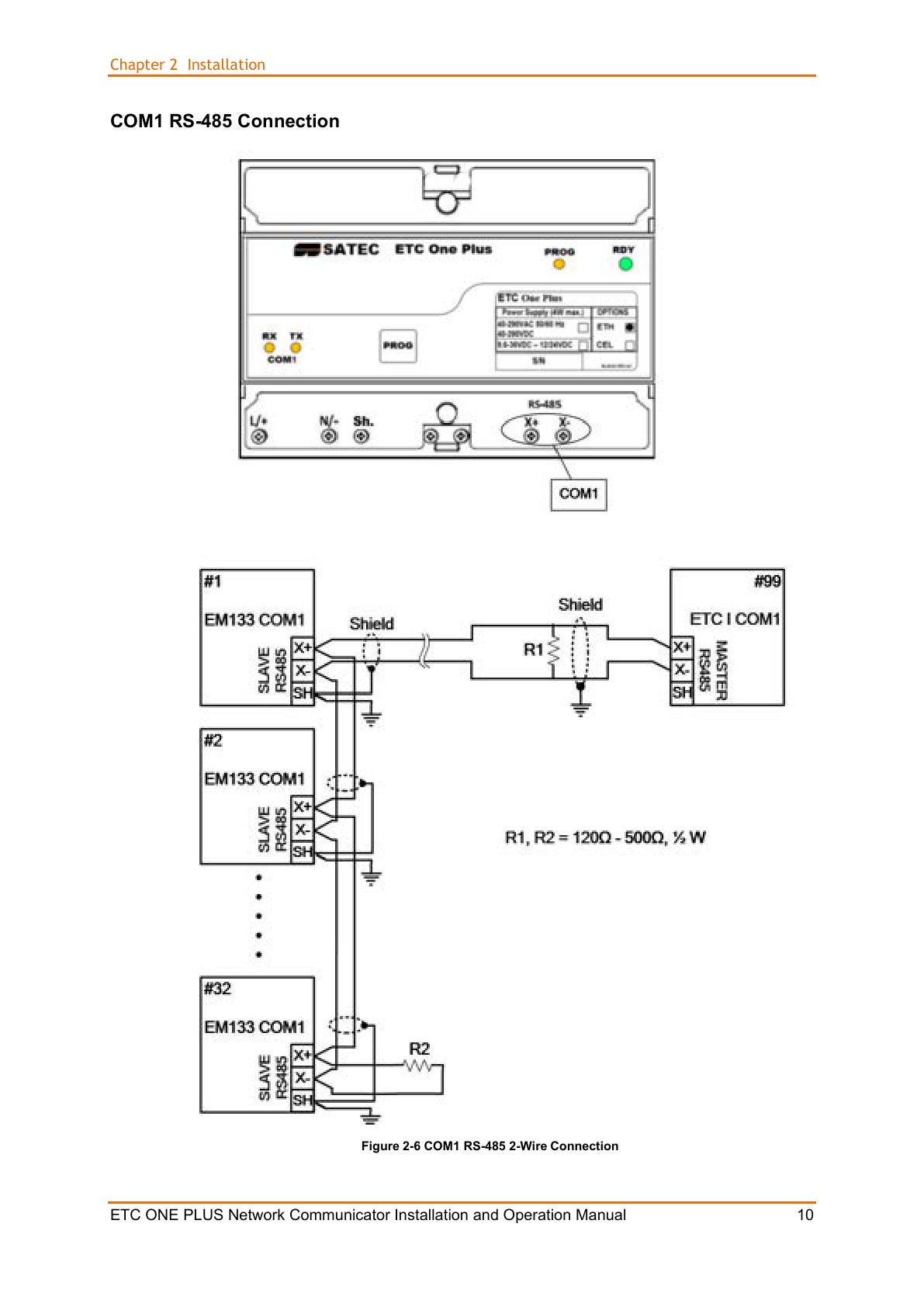
Check wiring against the full manual drawing
Open the full page so earth and shield connections remain visible. These diagrams are documentary evidence, not an approval of a site installation. Inspect the fitted connector labels and meter manual alongside the gateway manual.
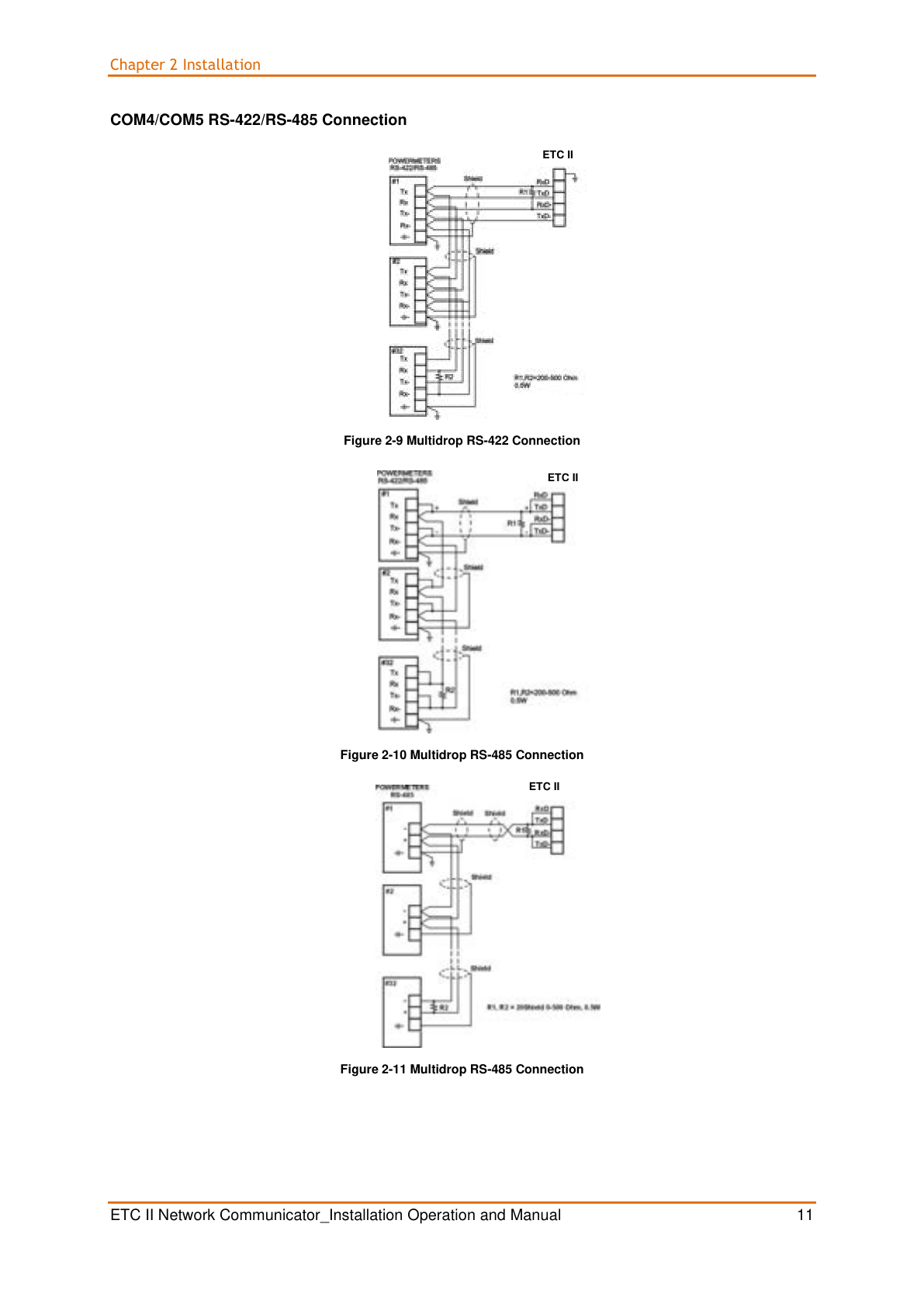
This copy has low-resolution embedded drawings. Exact terminal polarity and resistor text need clearer evidence before a detailed redraw or wiring instruction.
ETC II Network Communicator Installation and Operation Manual · BG0594 Rev A5 · p11
Open manual page
The drawing identifies X+, X− and SH. Do not substitute another vendor's A/B notation without checking polarity, or turn this drawing into a universal resistor or bonding instruction.
ETC ONE PLUS Network Communicator Installation and Operation Manual · BG0596 Rev A2 · p10
Open manual page
Full pages retained to preserve earth/ground context. Wiring implementation depends on the exact product variant, downstream meter documentation and installation design.
Find the failing part of the path
| Observation | What it establishes | Next check |
|---|---|---|
| No local meter response | The downstream test has not passed. | Check exact meter address, readable register, protocol, serial format and confirmed wiring. Preserve the raw timeout/exception. |
| ETC responds, meter does not | The client can reach the gateway; the meter path is unproven. | Check target slave address, reserved ETC address, route, correct serial port and operating mode. |
| Local read works; forwarded read fails | The meter responded in the local test. | Compare the forwarded request with the working request, then inspect routing and serial setup. |
| Pass-through works; Data Server value is absent or old | Forwarding worked for that request. Cache acquisition remains unproven. | Check global and exchange polling enables, source register/count, mapped exchange, decoded status and record freshness. |
| Value is plausible but differs from the meter | A response arrived; interpretation may still be wrong. | Check register basis, word order, type, scaling, selected meter and stale cache. |
| Failures appear as devices/clients are added | The result depends on the expanded arrangement. | Check duplicate addresses, connection load, response timing, routing and documented termination/shield installation. Record which addition changes the result. |
| RX/TX LEDs flash | Traffic is present. | Read the response and exception details. Activity does not prove valid data. |
Engineering fault-isolation matrix, not a confirmed diagnosis. LED activity: ETC II IOM p13; ETC ONE PLUS IOM p13.
Record the evidence before handover
Handover checks
- Exact model, firmware, supply and modules recorded.
- Gateway and meter addresses, routes and serial settings recorded.
- Original PAS configuration backed up.
- Known meter register read succeeds locally and through the intended path.
- For Data Server use, status and freshness verified against the mapped exchange.
- Upstream consumer receives correctly interpreted data during the agreed observation period.
Use the check record for handover.
Watch the gateway explainers
Michael explains the identification checks, forwarding path and ETC II Data Server checks. Use these summaries with the complete guide and the cited manuals.
30-second summary
Duration 0:30, measured from the file.
ETC gateway: choose the correct test.
Transcript
First, identify your SATEC gateway from its nameplate. ETC II can forward meter requests and can also collect readings in its Data Server. These need different tests. Prove one meter locally, then check the complete path. For collected data, verify status and freshness, not just the value. Use the matching manual and keep earth and shield connections visible.
92-second technician explainer
Duration 1:32, measured from the file.
ETC gateway: practical commissioning explainer.
Transcript
Start with the gateway nameplate, fitted interfaces and firmware. These pictures help you recognise the product family. They do not prove the supply rating or the installed communications option. ETC II supports pass-through gateway service and an embedded Data Server. Both functions can coexist. ETC One Plus is covered here as a pass-through gateway. Keep the two commissioning paths distinct. Before changing anything, record the settings and read a backup. In PAS, Upload Setups reads from the device. Send writes to it. First prove one downstream meter with a documented, read-only register request. For pass-through, match the serial settings and check the route. Use one client to read that same meter register through the gateway, with the intended meter address. A ping or flashing light is not proof of valid meter data. For the ETC II Data Server, check the global enable, polling interval and exchange settings. Record the source meter block and the different destination exchange address shown by PAS. The upstream client reads the exchange using the ETC address. Decode the status, timestamp and sequence before accepting stored data. Nonzero status alone does not mean success. Changing exchange sizes can move later addresses, so review the upstream map before making changes. For wiring, use the exact model drawing with earth and shield details visible. Confirm unclear labels with product support. Then add and test the remaining meters individually. Keep the completed worksheet and the matching manual pages.
Review-draft videos with real product photographs, logical diagrams and manual-page references. Human listening and publication review remain pending. YouTube publication links will be added after release.
Manuals and page references
These technical references were checked on 6 November 2026. Printed page numbers match PDF viewer page numbers in these copies. Documentary verification does not establish the configuration or condition of an installed device.
| ID | Document / revision | Pages | Evidence used |
|---|---|---|---|
| M1 | ETC II Network Communicator — Installation and Operation Manual BG0594 Rev. A5 | Installation pp9–12; operation/routing pp13–18; PAS pp30–33; serial/network pp37–39; routing pp43–44; Data Server pp48–51 | Model: ETC II |
| M2 | ETC II — MODBUS Communications Protocol Reference Guide BG0595 Rev. A2 | Register notation p5; acquisition/exchanges pp7–9; exchange layout p12; setup/routing pp21–23 | Model: ETC II |
| M3 | ETC ONE PLUS Network Communicator — Installation and Operation Manual BG0596 Rev. A2 | Installation pp9–12; modes pp13–14; settings pp16–18; PAS pp22–24; predefined routing p27 | Model: ETC ONE PLUS |
This guide is scoped to the supplied manuals and standard Modbus branches. ETC II factory-set M-Bus configurations require a separate procedure: COM4 may be dedicated to M-Bus. See ETC II IOM pp55–56.
If it still does not work
Prepare a nameplate photograph, a wide wiring photograph and close-ups with all communication and earth labels visible. Include the topology, firmware/PAS version, settings export, address schedule and failed request/response.
For an ETC II Data Server case, add the exchange configuration, mapped address, decoded status, timestamp and sequence. State whether the same meter read worked locally and through pass-through.
Keep credentials and access keys out of screenshots and exports supplied for review. A product specialist can then investigate the demonstrated failing stage.