
PM180 · BATTERY MAINTENANCE
How do I replace the backup battery in a PM180?
Quick Answer
The PM180 uses a CR1225 lithium 3.0 V coin cell. SATEC Australia recommends replacing it during planned servicing, with the instrument powered off, by a qualified person. The holder is on the CPU panel, close to the neighbouring power-supply terminals.
Factory clarification is pending. The Installation Manual's battery chapter permits replacement while powered, but its general precautions require all incoming AC and other power sources to be off before work. This guide follows SATEC Australia's powered-off servicing recommendation and does not give a live replacement procedure.
Before You Begin
Only qualified personnel familiar with the instrument and associated electrical equipment should perform this work. Follow the site's approved isolation and safety procedure; switching off one supply may not isolate every source. Do not open an energised CT secondary circuit.
Have the replacement cell and a small flat screwdriver ready. If the instrument's data matters, arrange a PAS upload before the shutdown. The Installation Manual refers to PAS upload and restore, but this guide does not provide a restore procedure.
The battery chapter allows replacement within 30 minutes after the power supply is switched off without losing data. It does not identify which data it means, or establish what happens after that interval. Do not treat this as a guarantee that every setting or record survives an extended batteryless shutdown.
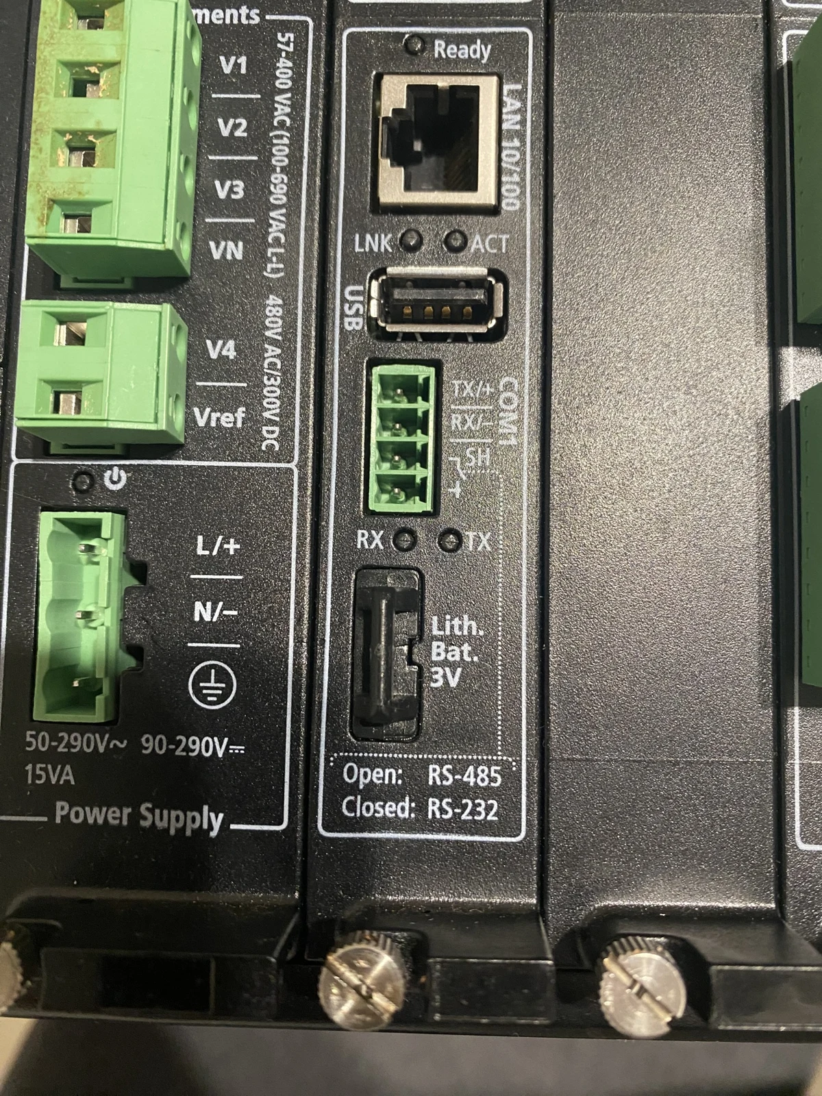
Replace The Battery
Proceed only after the qualified person has established safe conditions under the site's isolation procedure. The battery-only procedure uses the holder at the CPU panel face; do not open the case or remove the CPU card.
- Use the flat screwdriver to ease the battery holder out of the CPU panel.
- Remove the old cell from the holder.
- Fit the new CR1225 cell with the correct polarity, using the holder markings and the manual's battery figure. If the orientation is unclear, stop and contact SATEC Australia before fitting it.
- Insert the holder, with the new cell, into the CPU-panel battery compartment.
- Push the holder in until a click is heard.
Do not force a stiff holder or improvise a pliers procedure. Contact SATEC Australia if the holder cannot be withdrawn as shown in the manual.
The Installation Manual's photographs are in chapter 4, printed page 27 / PDF page 31.
Check The Result
Once power is restored through the site's normal procedure, check the clock and recent logged records in PAS. If data was uploaded beforehand, compare against that copy.
For an existing Modbus monitoring setup, the guide identifies lithium battery voltage as point ID 0x150B. Use the applicable register table to obtain its register address; the point ID is not a register address. Compare the voltage reading before and after the change if available. This guide gives no numerical low-battery acceptance threshold.
The manual describes a longer first start after battery installation. Whether that also applies to a routine replacement made with power off is awaiting factory clarification; this guide does not specify a normal replacement restart time.
When To Replace It
The Installation Manual describes a BATTERY LOW flag and an Event Log entry when the cell falls below its minimum level. A new PM180 is supplied without its battery fitted, so the installer fits the cell during installation.
If Something Is Not Right
Contact SATEC Australia support with the instrument's serial number and order code, a photograph of the CPU panel and holder, the shutdown duration, and the Event Log entries around the change. Include the battery-voltage readings if available.
Manuals And Source Pages
- PM180 Installation Manual, BG0521 Rev. A10, June 2025: precautions PDF page 2; battery chapter printed page 27 / PDF page 31. Open the manual in a new tab.
- PM180 Operation Manual, BG0525 Rev. A7, April 2019: memory context, printed pages 8 and 23 / PDF pages 9 and 24. Open the manual in a new tab.
- PM180 Modbus Communications Protocol Reference Guide, BG0527 Rev. A11: lithium battery voltage at PDF pages 32 and 62. Open the guide in a new tab.
Source review: 22 November 2026. Scope: the PM180 CPU-panel holder shown in BG0521 Rev. A10 and the supplied photographs. Older hardware revisions have not been checked.